Throwing Ball Robot Arm Design
Summer '22 technical skills: Arduino, Solidwork, FEA simulation, PID control, MATLAB, Simulink
The project requires us to design, build and integrate a simple robot arm to throw the ball to the required bin (ranging from 75-200cm) using a DC motor. There are three sections involved: mechanical, electrical and control aspects of this project.
For the mechanical design, our goal is to build minimize the weight of the space frame (robot arm) and moment of inertia while also maintaining stiff enough to withstand a 10N load. The length of the space frame is 20cm as required by the project requirements.
Thus, inspiring from the design of trusses, we come up with our own design and running through FEA to verify

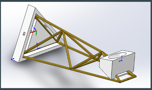
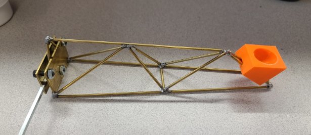
Then, after verified with our Solidwork model, we began to weld the arm. In addition to the space frame, we also designed and 3D-printed our own ball holder for better stability of the ball.
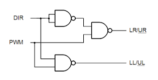
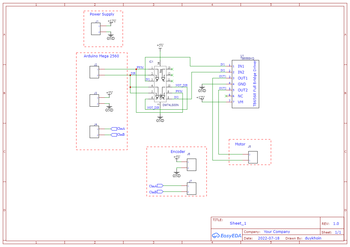
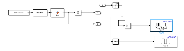
Moving on, after finished with the mechanical design, we start looking at the design of our own DC motor. For the motor controller, we used an H-bridge with a NAND gate to run the PWM and Direction of the motor. In addition, we use Arduino Mega 2560 to send PWM signal and GPIO to set the control.
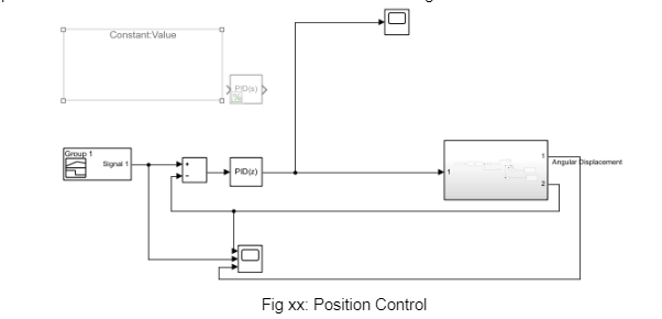
The control of Arduino is then performed in Simulink using the Renesselaer Arduino Support Package (RASP). This makes tuning the PID control easily as it allows real-time tuning. There are 2 strategy for controlling the arm, position and velocity control but they do share one common principle:
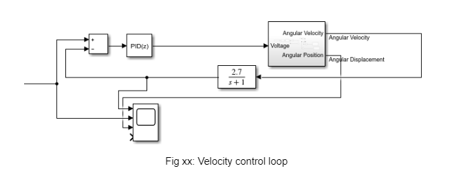
launching the ball from certain angle and then reduce speed to create a huge negative acceleration, which in turn provide the required force for the ball to launch from the robot arm. However, one key different is that for throwing the ball, we want the arm to rotate at high speed for long range. Thus, positional control is excel at high accuracy while velocity control is better for high range
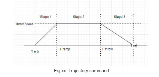
 In addition, our strategy to throw the ball is to use velocity control. First we will slowly move the arm to the desired starting angle. Then based on different distance from the test stand to the required bin, the arm will move at constant rotational specified
and stop at the desired launching angle.
In addition, our strategy to throw the ball is to use velocity control. First we will slowly move the arm to the desired starting angle. Then based on different distance from the test stand to the required bin, the arm will move at constant rotational specified
and stop at the desired launching angle.
The motor control has been tested successfully within Simulink, and the implementation on the motor is verified. The performance before the PID implementation of the tuning and smoothing on motor control is not as desired, after having the PID, the PID can reduce the oscillation and achieve a more ideal outcome. However, the position control of the motor can be more precise, and tuning from PID is necessary, the angular velocity though has a better-tuned result compared to the position control. Thus we wish we can achieve a more stable output from the motor, as then the motor will be able to halt or spin in the direction we want more accurately.